So the first question on your mind is probably what exactly is this thing?
My high school physics teacher, Mr. Roberts, was very dear to me and anyone else who spent time in his class. Mr. Roberts was a retired civil engineer who had earned his teaching certification and taught all of my school's physics classes. One thing that set his classes apart from any others that I have taken before or sense was the massive quantity of "demos" that he presented in class. These were short demonstrations that showed the practical effects of some physics concept that was part of the course curriculum. While I was still in class I had the idea of creating an instrument that could display in large-format a wide variety of different measurements that were relevant to the various physics topics that were demonstrated. I actually spent a couple of years brainstorming this project before I began serious efforts to build it. The project was kickstarted when I scored a good deal on the large LED matrix that makes up the display of the device.
The signature component is the 32x32 addressable led matrix that makes up the front of the device. This display has over 1000 very bright RGB leds that can be used to display text and graphics. Text at the default font size is readable from over 100 feet away. Displays like this are normally chained together in huge arrays to form "jumbotron" style screens in sports stadiums and the like. Luckily I was able to find some library code that gave me an easy way to draw text and such to the display. The display also has an array of threaded screw holes on the back which makes up the main chassis of the whole unit.
To drive the display I designed a mainboard that mounts several different modules and contains the power supply for the whole board.
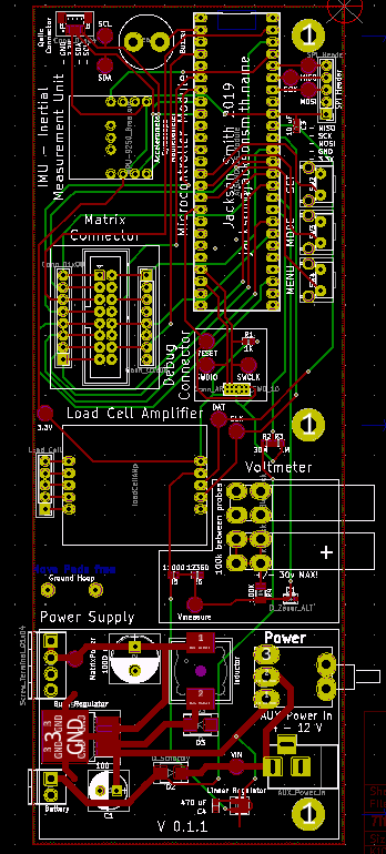
In order to accelerate the design process I used several pre-existing modules where it made sense. The main microprocessor, an ATSAMD21G, is mounted on a module that I designed the includes the processor itself as well as several closely related support components. I purchased an HX711 and an MPU 9250 breakout board from Sparkfun an incorporated those into the design.